


By Pass Rotameter
Bypass Type Rotameter Manufacturer
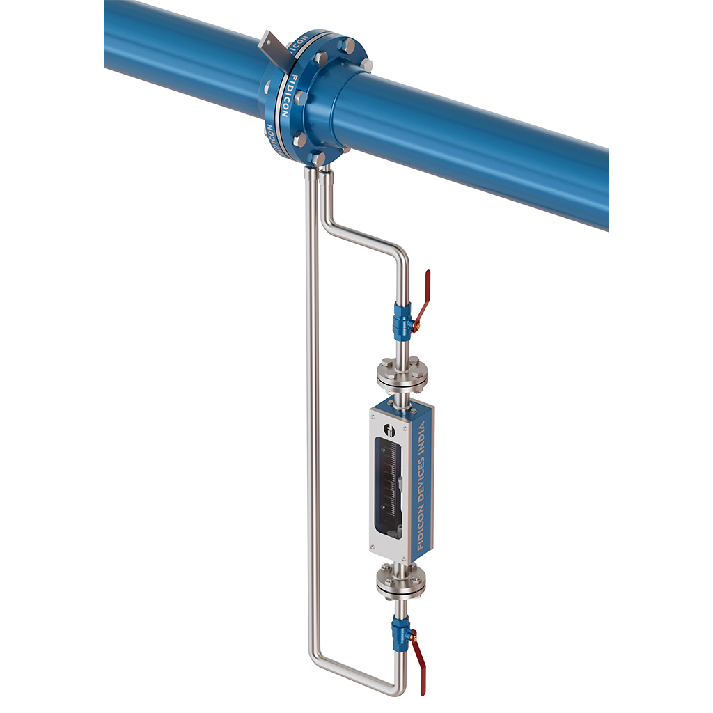
By Pass Rotameter is arrangement of Conventional Glass Tube Rotameter and Orifice Assembly Mounted in between the High Flowrate Line, it uses Pressure Head Difference to Indicate Flowrate. This devices is majorly preferred option after Flowrate measurements over 50000 LPH flow. It can be customised as per customer flow requirements.
Bypass Rotameter Introduction
A bypass rotameter is a kind of variable area flow meter that is used to measure high flows by diverting some of the fluid through a secondary bypass line with a rotameter. The method can be used to measure accurately without placing the rotameter in-line at the full process flow, pressure, or temperature.
Bypass rotameters are generally applied in a large pipe where the direct measurement of the flow is impractical or impossible, or it would necessitate a too-big flow meter. Rather, a primary orifice plate, flow nozzle, or restriction is placed in the main pipeline to impose a pressure drop that causes a proportional amount of fluid to flow into the bypass line.
What are Bypass Metering Components?
A bypass metering system is made up of several different parts which are used to measure the flow of a main pipeline by diverting a small amount of the fluid through a bypass line. Its main parts are:
Mainstream Flow Element (Orifice Plate/Flow Restrictor)
Causes a regulated pressure drop across the main pipeline
Pumps some of the fluid into the bypass line
Calculates the proportion of flow to measure correctly
Loop (Piping Loop)
An alternate route that transports a part of the fluid in the main line to the measuring device
This is designed to have a constant pressure and flow relationship.
Variable Area Flow Meter Rotameter
It was fitted in the bypass line to gauge the diverted flow.
The flow measured is then related to the total mainline flow.
Isolation Valves and Control Valves
Employed as a control of the flow through the bypass line
Allow maintenance, calibration, or emergency shutoff without interfering with the principal process.
Differential Pressure Ports/Pressure Tapping Points
Mounted in front and behind the main component
Assist in the observation and control of proper differential pressure and correct bypass flow.
Flow Transmitters or Indicators
Offer either digital or analog output signals to be used in remote monitoring or process control system interfaces.
These devices combine to give a cost-effective, safe, and precise flow measurement solution to high-flow pipelines where direct metering would be uneconomical.
Operating Principle of Bypass Rotameter
A bypass rotameter operates on the principle of differential pressure and variable area flow measurement. Here’s how it works:
Flow Division:
A primary restriction element (such as an orifice plate or flow nozzle) is installed in the main pipeline. This restriction creates a pressure drop between two tapping points.
Bypass Loop Activation:
This pressure difference drives a proportional flow of the process fluid through a bypass line connected across the two tapping points.
Flow Measurement:
The diverted flow enters the rotameter in the bypass line, which consists of a tapered tube and a float. As the flow increases, the float rises to a height where the upward force of the fluid equals the weight of the float—indicating flow rate.
Mainline Flow Estimation:
Since the bypass flow is proportional to the mainline flow (based on calibrated conditions), the total flow can be inferred using the bypass measurement.
Standard Features of a Bypass Rotameter
Tapered Tube and Float:
Clear or metal pipe with a floating element to show that flow is present visually or electronically.
Bypass Line Setup:
Has inlet and outlet valves, frequently with filtering to avoid clogging.
Primary Flow Element (Orifice/Nozzle):
Establishes controlled differential pressure required to properly flow bypass.
Flow Indicator/Transmitter:
Mechanical pointer or electronic sensor of local or remote flow readings.
Accessories to be mounted:
Brackets, fittings, and connectors to allow incorporation into high-pressure or large-diameter pipelines.
Calibration:
Every system is adjusted to guarantee that bypass flow is a faithful indicator of mainline flow.
Long-lasting materials:
Can be had in SS, brass, or corrosion-resistant plastics, and suitable for industrial applications.
Dumping of Bypass Rotameter
Disposing of a bypass rotameter is necessary, and it must be done in a proper manner to avoid environmental hazards and adhere to the regulations of managing wastes. This is how it could be done in a responsible manner:
Decontamination
Clean the rotameter and bypass assembly and ensure that all the process fluids are removed before disposal. This is particularly crucial when the meter has been exposed to dangerous, toxic, or corrosive chemicals.
Take Apart the Parts
Disaggregate the system to the component parts:
Rotameter tube and float
Fittings and valves
Orifice plate or nozzle
Housing components metallic and plastic
The materials should be sorted.
Division by the type of material:
Metal components (stainless steel, brass, etc.) can be delivered to metal recycling departments.
Glass tubes must be treated as laboratory glass waste.
Plastic parts should be discarded according to the local plastic waste regulations.
Electronic components (where available) ought to be sent to e-waste recycling.
Act in accordance with local disposal regulations.
Make sure that proper disposal is done as per the instructions of the local environmental agencies. Wherever possible, certified industrial waste handlers or recyclers must be employed.
Record Disposal
In case your industry or facility mandates it, keep a record of the disposal process consisting of:
Disposal date
Technique employed
Contractor information (in case of any)
All decontamination certificates
Safe and controlled disposal of flow meters such as bypass rotameters safeguards the environment and makes the workplace compliant. Want a sample SOP (standard operating procedure) of this?
FAQs
A bypass rotameter is a flow measuring device that is used to measure high flow rates indirectly by causing a small, proportional flow of the fluid to be diverted to a second line (bypass), where the flow is measured by a standard rotameter.
It operates by developing a difference of pressure in the main pipeline through a flow restriction (such as an orifice plate). This pressure drop causes a known small amount of fluid to force its way through a bypass line that has a rotameter in it to measure the flow. This reading is then matched with the total flow in the main pipeline.
Where direct measurement cannot be made, as with large pipelines or high-pressure systems, a bypass rotameter is employed. It permits precise, cost-effective flow measurement without the requirement of an oversized or costly mainline meter.
Yes, bypass rotameters are able to measure liquids, gases, or even steam, provided they are calibrated correctly. Nevertheless, the fluid should be clean and should be compatible with the meter materials to perform consistently.
The most important ones are
- Proper fitting of the orifice or restriction element
- Wash bypass line and rotameter tube.
- Constant pressure and temperature during the process
- Correct calibration with respect to main line flow
- Cleaning of the float and tube
Inspection of leakages or corrosions
- Facilitating the free flow of floats
- Ensuring that bypass lines and pressure tappings are not blocked
Bypass rotameters have sturdy materials such as stainless steel, which are able to withstand high-pressure environments. Also, they are incorporated with a primary orifice so that the process of handling pressure drop is optimized.
Yes, it is perfect in continuous flow monitoring. The float in the bypass tube is clearly visible, and the flow rate can be monitored continuously in real-time without disturbing the main flow.
Bypass rotameters are fairly accurate with a tolerance of approximately +/-1.6 percent to +/-2.5 percent full scale, depending upon model and calibration. They are particularly good at indicative or trend monitoring.
Yes, bypass rotameters can be safely operated with corrosive or aggressive process fluids when made with corrosion-resistant materials such as PTFE linings or stainless steel.
Numerous contemporary bypass rotameters might be available with choices of electronic transmitters or alarms and may be incorporated into PLC or SCADA systems to be monitored and controlled remotely.
Bypass rotameters can be dismantled and discarded in an environmentally responsible manner, particularly when they were exposed to hazardous or corrosive fluids.
Yes, most of the parts, like the metal body (e.g., stainless steel), glass tubes, and electronic parts, can be dismantled and taken to recycling according to the local recycling options.
Make sure that the rotameter is cleaned, decontaminated (in case it was used with toxic or hazardous fluids), and depressurized before disposal. Electrical connections should be disconnected as well in a safe manner.
Yes, in case the bypass rotameter has electronic transmitters or sensors, they should be disposed of as electronic waste (e-waste) according to local e-waste disposal regulations.
Recording the process of disposal for audit, environmental compliance, and traceability purposes is good practice, especially in an industrial environment, especially when hazardous substances were used.
The general components of a bypass metering system are an orifice plate or primary flow restrictor, bypass piping, a rotameter (or flow indicator), isolation valves, and occasionally a differential pressure transmitter.
The orifice plate causes a pressure drop in the main pipeline, diverting a proportional flow through the bypass line to the rotameter to be measured.
The flow of the bypass line is controlled by isolation valves. They enable one to maintain or calibrate the rotameter without stopping the main process flow.
Yes, bypass systems can be equipped with pressure and temperature sensors to improve the accuracy of the measurements, particularly when compensating flow readings under different process conditions.
The bypass piping should be so designed that there is a stable and proportional flow through the rotameter. Measuring errors may be caused by inappropriate pipe diameter, poor alignment, or turbulence.
